Learning outcomes:
The graduate of the course understands the principles of transmission and propagation and processing of high-frequency energy. Knowledge and understanding
After completing the course the student:
– knows the basic physical processes that occur in high frequency processes,
– knows the basic properties and principles of passive and active high frequency circuits,
– knows the methods of lossless transmission of high frequency energy. Acquired skills and competencies
– ability to analyze and synthesize passive high-frequency devices such as lines, radiators, splitters, combiners, and signal routers,
– ability to match a load to a generator,
– ability to measure high-frequency circuit parameters,
– ability to diagnose large-scale high-frequency systems,
– ability to design a high-frequency path in an antenna counting system,
– ability to design a high-frequency path in an antenna counting system, – ability to design a high-frequency path in an antenna counting system, – ability to Ability to design a solution, defend the solution, present the solution, and work collaboratively in a team to implement the solution.

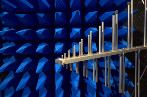
The picture shows a view of the waveguides that are used on the radio relay northern route in Slovakia to transmit data (internet, video, audio) from the transmitting site Bratislava Kamzík to the east of Slovakia. The principle of operation of the waveguide is also part of the teaching in the subject High Frequency Technology.
What good is that ?
You will be one of the few professionals who understand the practical applications of electromagnetic fields. Not just the equations, but especially where the fields are used, what elements are used to design them, how current and voltage are converted to electromagnetic fields and vice versa. I’m sure all of you have a cell phone. This is such a small demonstration of what radio frequency technology is good for. You are in contact, pretty much every place on earth, and for that to be the case, there must be experts in high frequency technology. I’m sure you’ve heard about 5G about Starlink about microsatellites, … and that’s a big challenge for both the subject content and the research that follows.

Why choose this subject:
Exercises a little differently
In the exercises, students of the radio frequency technology course will learn to work with ANSYS Electronics software, Smith diagram and simulate the basic (simplest elements) of radio frequency technology. The exercises will not remain only in theoretical terms, but all the elements simulated will be produced or made by the students themselves (e.g. in JCL PCBs). Finally, they will measure the finished microstrip devices with a circuit analyzer and compare them with the desimulated values.
In this video we can see what Ansys Electronics Desktop, one of the most advanced tools for simulating electromagnetic problems, can do. Also available for students in the computer lab is the AWR Microwave Office program, which can be said to be the industry standard in microwave circuit design.

You design, build, measure, evaluate
The course focuses mainly on the understanding and practical implementation of microwave circuits.
| Lectures | Exercises | Practical exercises | Measurements |
|---|---|---|---|
| Introduction, elementary fields and waves | Smith diagram | Ansys HFSS | S parameters |
| Skin effect | Serial customisation | Microstrip | Network analyzer |
| Long lines | Parallel adaptation | Parallel matching | Microwave circuit wiring |
| Impedance matching | Multisection transformers | Willkinson divider | With parameters of designed and constructed circuits |
| Microwave transmission lines | Broadband divider | With parameters of designed and constructed circuits | |
| Planar lines | Hybrid | With parameters of designed and constructed circuits | |
| Elements with concentrated parameters | Balun | ||
| Wilkinson, hybrid, directional tap | Patch antenna |
What else fits
Smith diagram
In 1933, Philip Smith designed and published a graphical tool to simplify the calculation and solution of impedance transformation problems on lines. Since computing technology was not at a sufficient level at that time (and for many years afterwards), Smith’s diagram became one of the most widely used aids in the development of high-frequency circuits. Although modern simulation programs nowadays solve the tasks much more efficiently, the Smith chart remains a very useful tool, especially for displaying the results of measurements and simulations.

The Smith diagram is a representation of the reflection coefficient in polar coordinates, into which the impedance (z = r + jx) and/or admittance (y = g + jb) plane is then mapped. Denoting each variable with lower case letters tells you that all values on the diagram are normalized to the system’s reference impedance Z0 (most commonly 50 Ω).
And should you need more information regarding this subject or need to add some interesting links, feel free to get in touch.
Prerequisites for the courses Electrical Engineering and Electrical Engineering 1
Exercises from the subject Electrical Engineering and Electrical Engineering 1:
- Laboratory exercises that will focus on the calculation, measurement and simulation of electrical circuits. You can earn 15 points for handing in your lab reports.
- There will be 2 credit essays during the semester – one about halfway through and the other before the end of the semester. You can earn 2 x 10 points for the credit essays.
- You can earn a maximum of 35 points in total for the exercises and these points will be included in the exam.
Prerequisites to take the exam:
- You must submit all lab reports in the required form and quality.
- You must earn at least 15 points to qualify for credit.
Exam
1. Results during the semester (exercises): max. 35 points
- For the processing of laboratory reports (15 points)
- Credit essays (20 points)
2. Examination (practical + written + oral part): max. 65 points
- The examination will be conducted in written form by full-time study. Alternatively, the written attendance form of the examination may be conducted by means of a test using MS Forms.
- The exam is designed to cover the theory of the subject to a small extent and the skill of counting examples to a greater extent.
- You will be informed about the exact form of the examination in the subject Electrical Engineering and Electrical Engineering 1 at the last lecture.
———————————————————————————————
Total (Results during the semester + Exam): max. 100 points
Rating:
| A | excellent | <92-100> |
| B | very good | <83-92) |
| C | good | <74-83) |
| D | satisfactory | <65-74) |
| E | sufficiently | <56-65) |
| FX | Insufficient | <0-56) |
Linked to science and practice
A set of different measurements is carried out in the radio frequency laboratory. In the picture we see the calibration of a stripline line using a high-frequency probe, which was also developed at the Institute of Electrical Engineering. The calibrated stripline will serve as a reference electromagnetic field source for further measurements and calibrations. The measurement is part of the dissertation solution.

Also for such research tasks, graduation in high-frequency techniques gives a good foundation.
SUBJECT TEACHERS


Join more than 100 students who study at the Institute of Electrical Engineering
Be part of ÚE and start your career.